A tap hole chart is a useful reference for selecting the appropriate hole diameter before creating internal threads with a tap. Choosing the right hole size is an important step in machining because the drilled hole determines how much material remains for the tap to form the internal thread.
Whether you are working with metric threads, UNC threads, or UNF threads, a tap hole chart can make hole preparation faster and more consistent. By matching the required thread size with its pitch or threads per inch (TPI), you can identify an appropriate starting hole diameter before tapping.
However, a tap hole chart should be treated as a reference rather than a universal rule. The appropriate hole diameter can vary depending on the thread standard, desired thread engagement, material, tapping method, tap design, and application. For precision or safety-critical work, always verify the dimensions against the applicable engineering standard or tool manufacturer’s recommendations.
What Is a Tap Hole Chart?
A tap hole chart is a reference table that helps identify the drill diameter used to prepare a hole for internal threading. It typically connects a thread specification with a pitch, TPI value, and recommended tap hole diameter.
The terminology can vary between machining references. A tap hole generally refers to the hole prepared before a tap is used to create internal threads. The chart may therefore also be described as a tap drill chart, tapping drill chart, or tap drill size chart.
Depending on the chart, information may be organized by:
- Metric thread size
- Metric thread pitch
- UNC thread size
- UNF thread size
- Threads per inch (TPI)
- Recommended drill or tap hole diameter
- Metric and inch equivalents
The exact values should always be checked against the relevant thread specification and application requirements.
Why Is Tap Hole Size Important?
The diameter of the prepared hole affects the amount of material available for forming the internal thread. A hole that is too small can make tapping more difficult, while a hole that is too large may reduce the amount of thread engagement.
When the Hole Is Too Small
An undersized hole leaves more material for the tap to remove or form. Depending on the material and tapping method, this can increase cutting forces and make the operation more difficult.
Excessive tapping load can contribute to poor thread quality, accelerated tool wear, or tap failure.
When the Hole Is Too Large
An oversized hole leaves less material for the internal thread. This can reduce thread engagement and may result in a thread that does not meet the intended specification.
When the Hole Is Properly Prepared
A suitable tap hole provides a practical balance between thread formation, tapping load, and the requirements of the finished connection. The exact target depends on the thread specification and application.
How to Read a Tap Hole Chart
A tap hole chart can look complicated at first, but most charts use a small number of key measurements.
Thread Size
The thread size identifies the nominal diameter and thread specification. Metric threads commonly use an M designation, while inch-based threads may use numbered or fractional sizes.
Pitch
For metric threads, pitch is the distance between corresponding points on adjacent threads. It is normally expressed in millimeters.
The same nominal metric diameter can be available with different pitches, so it is important to identify the complete thread specification rather than relying only on the M diameter.
Threads Per Inch
In many inch-based thread systems, thread density is expressed as threads per inch, or TPI. The TPI value should be matched with the correct thread diameter and series.
Tap Hole Diameter
The tap hole diameter is the size of the hole prepared before tapping. Depending on the reference, the value may be displayed in millimeters, inches, or both.
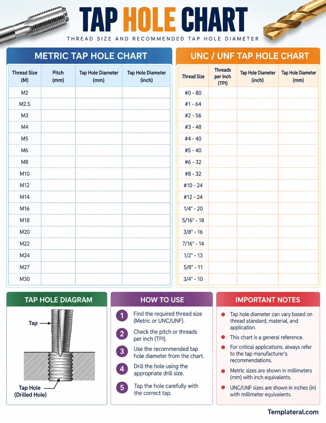
Metric Tap Hole Charts
Metric tap hole charts are commonly organized according to nominal thread diameter and pitch. A typical metric thread designation contains the letter M followed by the nominal diameter and, when necessary, the pitch.
For example, two threads can share the same nominal diameter but have different pitches. Because pitch affects the thread geometry, the corresponding tap hole requirement can also differ.
Metric Coarse Threads
Coarse metric threads are commonly used for general-purpose fastening and machining applications. When selecting a tap hole for a coarse thread, identify both the nominal diameter and the specified coarse pitch.
Metric Fine Threads
Fine metric threads have a smaller pitch than their corresponding coarse versions. They may be selected when a particular application requires finer thread spacing or other design characteristics.
Never select the tap hole based solely on the nominal metric diameter when the drawing or specification identifies a particular pitch.
UNC and UNF Tap Hole Charts
UNC and UNF are commonly encountered inch-based thread series within the Unified Thread Standard.
UNC stands for Unified National Coarse, while UNF stands for Unified National Fine. The thread designation identifies both the nominal size and thread count.
When using an inch-based tap hole chart, confirm both the thread diameter and TPI before selecting the corresponding hole size.
UNC Threads
UNC threads generally have fewer threads per inch than the corresponding fine thread series of the same nominal diameter. They are commonly encountered in general-purpose applications.
UNF Threads
UNF threads use a finer thread pitch than the corresponding UNC series. Because the thread geometry differs, the tap hole requirement should be selected specifically for the UNF specification.
How to Use a Tap Hole Chart
Using a tap hole chart is straightforward when the complete thread specification is known.
1. Identify the Thread Specification
Start by checking the engineering drawing, component specification, fastener requirement, or project instructions. Identify whether the required thread is metric, UNC, UNF, or another standard.
2. Confirm the Pitch or TPI
For metric threads, confirm the pitch. For inch threads, confirm the TPI. This prevents you from selecting a hole size for a different thread variant with the same nominal diameter.
3. Locate the Thread in the Chart
Find the matching thread size in the appropriate section of the chart. Then read across to the corresponding tap hole or tap drill diameter.
4. Verify the Recommendation
Before drilling, confirm that the chart is appropriate for the thread standard and intended application. For demanding work, compare the value with an authoritative engineering reference or the tap manufacturer’s technical information.
5. Prepare the Hole
Drill the hole using the selected diameter and appropriate machining conditions. Proper alignment, tool condition, and hole quality can all influence the final tapping result.
6. Tap the Hole
Once the hole is properly prepared, use the appropriate tap and tapping method. Follow the tool manufacturer’s guidance for cutting conditions, lubrication, and tapping technique where applicable.
Tap Hole Size and Thread Engagement
Tap hole selection is closely related to the amount of thread engagement required. The smaller the prepared hole, the more material remains available for the internal thread profile. However, maximizing thread engagement is not always the only consideration.
A smaller hole can increase tapping forces, while a larger hole can reduce thread engagement. The appropriate balance depends on the thread standard, material, application, and required mechanical performance.
For this reason, there is not necessarily one universal “best” tap hole diameter for every situation. The correct selection should follow the applicable specification and intended use.
Factors That Affect Tap Hole Selection
A general tap hole chart provides useful reference information, but real-world machining involves several additional factors.
Material
Aluminum, mild steel, stainless steel, brass, plastics, and other materials can behave differently during drilling and tapping. Material properties can influence cutting forces, chip formation, lubrication requirements, and tool life.
Tap Type
Different tap designs are intended for different applications. Hand taps, machine taps, spiral-point taps, spiral-flute taps, and other designs can have different operating requirements.
Blind and Through Holes
A through hole allows chips and the tap to pass through the material, while a blind hole has a limited depth. Blind-hole applications require careful consideration of thread depth, chip evacuation, and available clearance at the bottom of the hole.
Required Thread Engagement
The intended load and function of the threaded connection can influence the required thread engagement. Always follow the design specification when one is provided.
Tool Manufacturer Recommendations
For specialized tooling or demanding materials, the manufacturer’s recommended hole size and cutting conditions can be more appropriate than a generic reference chart.
Common Tap Hole Mistakes
Several mistakes can cause tapping problems even when a reference chart is available.
- Using the wrong thread standard: Make sure the selected chart matches the required thread system.
- Ignoring pitch or TPI: Nominal diameter alone may not identify the correct thread.
- Confusing tap diameter with hole diameter: The prepared hole is smaller than the nominal external diameter of the finished thread.
- Choosing a size without checking the application: General charts may not account for specialized materials or tooling.
- Failing to check hole quality: Poor drilling, excessive runout, or an inaccurate hole can affect the final thread.
- Ignoring manufacturer guidance: Specialized taps may have specific hole-size recommendations.
Tap Hole Chart vs. Tap Drill Chart
The terms tap hole chart and tap drill chart are often used to describe essentially the same type of reference. Both can provide the drill diameter needed to prepare a hole before tapping.
The terminology can vary between manufacturers, machinists, websites, and engineering references. When using a particular chart, focus on the definition of the columns and the thread standard rather than relying only on the title.
For practical workshop use, either term may lead you to the same type of information: the relationship between a thread specification and the hole prepared for tapping.
Tips for Using a Printable Tap Hole Chart
A printable chart can be especially convenient in a workshop because the information is available without opening a digital device.
- Print it at a readable size: Make sure thread sizes and measurements are easy to see.
- Keep metric and inch sections separate: This reduces the chance of confusing measurement systems.
- Place it near the work area: A chart near the drill press or machining station can be quickly referenced.
- Verify critical dimensions: Use an authoritative source for precision or safety-critical work.
- Protect the printed copy: A laminated or protected sheet can be easier to maintain in a workshop environment.
How to Choose a Reliable Tap Hole Reference
Not all online charts are equally suitable for engineering or production use. Before relying on a chart, consider whether it clearly identifies the thread standard, units, and basis for its recommendations.
A general-purpose chart can be useful for quick reference, but critical applications should be checked against the applicable thread standard, engineering documentation, or tooling manufacturer’s specifications.
This is especially important when working with unusual materials, specialized thread forms, high-load connections, or components where thread performance is critical.
Final Thoughts on Tap Hole Charts
A tap hole chart is a convenient reference for determining the appropriate hole size before creating internal threads. By identifying the correct thread size, pitch or TPI, and thread standard, you can use the chart to select a suitable starting diameter for the tapping operation.
The chart is most effective when used together with proper drilling practices, suitable tooling, and reliable technical specifications. Material, tap type, thread engagement, hole depth, and application requirements can all influence the final result.
For everyday machining and workshop tasks, keeping a clear printable tap hole chart nearby can make thread preparation faster and easier. For precision work, always verify the selected dimension against the applicable engineering standard or manufacturer’s recommendations before machining.
Download: Tap Hole Chart Template
